Test Your ESP32-S3 First, or Waste Three Days Like I Did
ESP32-S3 validation checklist before building your project. Test GPIO pins, avoid strapping pin mistakes, catch dead boards before wiring. Save hours debugging.
Key takeaways
- Before committing an ESP32-S3 to a project, verify the 3.3V power rail with a multimeter and confirm at least one GPIO blinks an LED. These two checks take five minutes and prove the board is functional.
- Strapping pins GPIO0, GPIO45, and GPIO46 affect boot mode and power supply configuration. Connecting external hardware to them can prevent the board from booting normally.
- On N8R8 variants with PSRAM, GPIO35-37 are used for the PSRAM interface and are not available for general use. On USB-enabled boards, GPIO19 and GPIO20 are reserved for USB data lines.
- On third-party boards or mission-critical projects, run a full GPIO sweep: cycle through every exposed pin with an LED and log the results. It takes 20 minutes and is the only way to find dead traces before they appear mid-project.
Fixes when it breaks. Workflows when it doesn't.
OpenClaw guides, configs, and troubleshooting notes. Every two weeks.
Why Validate Before You Build
I've been a test tech long enough to know: the most expensive mistakes happen when you assume your tools work. You wire up a circuit, write code, spend three hours debugging, only to discover the dev board was dead on arrival. Or worse, one GPIO pin is fried and you've built your entire prototype around it.
Fifteen minutes of validation saves hours of frustration. Before I commit an ESP32-S3 to a project, I test it systematically. Power rails, GPIO outputs, the pins that look usable but aren't. This isn't paranoia, it's process.
This guide walks through validating an ESP32-S3 DevKit before you trust it with anything important. If you're building an ESP32-S3 project, start here.
This article contains affiliate links. If you purchase through these links, Stack-Junkie earns a small commission at no extra cost to you. We only recommend products we actually use.
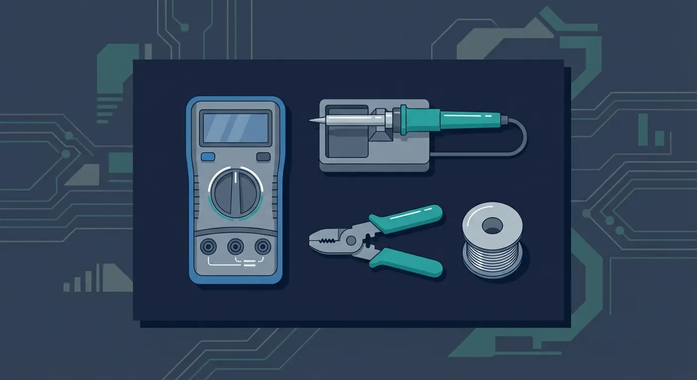
What You Need
The Board (ESP32-S3-DevKitC-1 or Variants)
I use the ESP32-S3-DevKitC-1. It's Espressif's official reference board with USB-C, plenty of GPIOs broken out, and decent documentation. There are cheaper clones, and most work fine, but if you're just starting out, the extra $5 for the official board buys you confidence that weird behavior is your fault, not the hardware.
The DevKitC-1 comes in variants. N8R8 means 8MB flash, 8MB PSRAM. That's more than enough for most projects. Check what you're buying.
Breadboard and Jumpers
Any breadboard and jumper kit will do. You need somewhere to prototype without soldering.
LEDs and Resistors (or a Multimeter)
An LED assortment with resistors is the fastest way to validate GPIOs. A multimeter works too, but LEDs give you instant visual feedback. I use 220-ohm resistors with standard 5mm LEDs.
Step 1: Power Verification
Plug in the USB-C cable. The board should enumerate as a USB device. On Linux, run dmesg | tail and look for a new ttyACM or ttyUSB device. On Windows, check Device Manager. On macOS, check /dev/cu.*.
If nothing shows up, try a different cable. Not all USB-C cables carry data.
Once the board enumerates, verify the 3.3V rail. Stick a multimeter probe on the 3V3 pin and ground. You should read 3.2-3.4V. If it's off by more than 0.2V, something is wrong with the regulator or your USB power supply.
Step 2: Basic Blink Test
Upload a Blink Sketch
Open Arduino IDE (or PlatformIO, or ESP-IDF, whatever you use). Install the ESP32 board support if you haven't already. Select ESP32S3 Dev Module as the board.
Load the basic blink example:
void setup() {
  pinMode(2, OUTPUT);
}

void loop() {
  digitalWrite(2, HIGH);
  delay(1000);
  digitalWrite(2, LOW);
  delay(1000);
}
Upload it. If the upload fails, check:
- Correct board selected
- Correct serial port selected
- Try holding BOOT button during upload (some boards auto-reset, some don't)
Once uploaded, the LED on GPIO2 should blink. Most DevKitC-1 boards have an onboard LED on pin 2. If it blinks, you've got a working CPU, working flash, and at least one working GPIO.
Move the LED to Different Pins
Now wire an external LED to the breadboard. Anode (long leg) to GPIO, cathode (short leg) to a 220-ohm resistor, resistor to ground. Change the pin number in the code. Try GPIO4, GPIO5, GPIO6. Upload each time. The LED should blink on every pin you test.
If a pin doesn't work, note it. We'll come back to that.
Step 3: The Pins to Avoid
Not all GPIOs are equal. Some have side effects. Some don't work at all. Here's what to know before you commit a pin to your project.
Strapping Pins (GPIO0, GPIO45, GPIO46)
The ESP32-S3 uses certain pins to determine boot mode and other configuration options at startup. These are called strapping pins. According to the ESP32-S3 datasheet and GPIO documentation, the key ones are:
- GPIO0: Boot mode. Pulled low at startup = download mode (for flashing). Pulled high = normal boot.
- GPIO45: VDD_SPI voltage. Used to select flash/PSRAM power supply. Don't connect external hardware here.
- GPIO46: ROM messages enable. Affects serial debug output at boot.
You can use GPIO0 in your project after boot completes, but if you wire a button or sensor that pulls it low, the board might fail to boot normally. I avoid GPIO0 unless I need a boot mode switch.
GPIO45 and GPIO46 are best left alone entirely.
USB Pins (GPIO19, GPIO20)
If your DevKitC-1 variant uses the USB peripheral (it probably does), GPIO19 and GPIO20 are reserved for USB data lines. Don't try to use them for GPIO. You'll lose USB functionality or worse, short something. See the USB OTG console documentation for details.
Flash/PSRAM Pins (if your variant uses them)
If your board has PSRAM (like the N8R8 variant), GPIO35-37 are used for the PSRAM interface. They're not available for general use. The ESP32-S3-DevKitC-1 user guide lists the exact pins used by your variant.
Check the schematic before assuming a pin is free.
Step 4: Systematic GPIO Sweep (Optional)
If you're building something mission-critical or you bought a third-party board, run a full GPIO sweep. Write a script that cycles through every exposed pin, sets it high, waits, sets it low, waits, and logs the result.
Wire an LED (with resistor) to each pin one at a time and confirm the LED blinks. If a pin doesn't respond, mark it as suspect.
This takes 20 minutes but it's the only way to be certain. I've found dead traces on cheap boards this way.
What If Something Doesn't Work
Board doesn't enumerate: Bad cable, bad USB port, or dead regulator. Try a different cable first. If still nothing, return the board.
Pin doesn't respond: Check your wiring. If wiring is correct and the pin still doesn't work, it might be configured for a peripheral (UART, SPI, etc.) at boot. Check the default pin configuration in the ESP-IDF documentation. Or the pin is genuinely dead.
Flashing fails: Hold the BOOT button (GPIO0) during upload. If that doesn't work, check serial monitor for boot messages. You might be in the wrong boot mode.
Weird behavior after wiring external hardware: You might have a strapping pin conflict. Disconnect everything and try again. Add components one at a time.
Validation Complete, Now Build
If power checks out, blink works, and you've noted the forbidden pins, your board is validated. You know it works, you know which GPIOs are safe, and you have a baseline to compare against if something breaks later.
Document what you tested. I keep a text file for every board: serial number (if it has one), date validated, which pins I tested, any quirks I found. When a project fails three months later, I can check if the board was ever good to begin with.
Now go build something. The board is ready. You've done the work up front. Meet Derek and the rest of the Stack-Junkie crew here.
FAQ
Does this apply to other ESP32 variants?
The process applies to any ESP32, but the strapping pins and reserved pins change between variants. ESP32 classic, ESP32-S2, ESP32-C3, etc. all have different pinouts. Check the datasheet for your specific chip.
Can I use a multimeter instead of LEDs?
Yes. Set the multimeter to measure voltage (DC, 0-5V range). Touch the probe to the GPIO pin and ground. When you set the pin high, you should read close to 3.3V. When low, close to 0V. LEDs are faster for visual confirmation, but a multimeter is more precise.
What if my board doesn't show up in the IDE?
Check drivers. Windows needs CP210x or CH340 drivers depending on the USB-to-serial chip. Linux and macOS usually work out of the box. If still no luck, try a different USB port or reboot. Some systems cache USB device states badly.
Are third-party DevKits okay or should I buy Espressif?
Third-party boards are usually fine, but quality varies. If you're learning or debugging a complex project, buy the official Espressif board first. Once you know what working hardware feels like, you can gamble on cheaper options. I've used clones successfully, but I've also thrown away clones that had intermittent shorts or mislabeled pins.
How do I know if a pin is safe for my project?
Check the schematic (if available), the datasheet, and the ESP-IDF GPIO documentation. Cross-reference all three. If a pin isn't listed as strapping, isn't reserved for USB or flash, and you've tested it with an LED, it's probably safe. When in doubt, test first.
Fixes when it breaks. Workflows when it doesn't.
OpenClaw guides, configs, and troubleshooting notes. Every two weeks.